Table of contents
Abstract
Designing a petrol (gas) station for a highway or road involves a comprehensive approach to ensure optimal safety, functionality, and visual appeal. Below is an in-depth guide outlining the step-by-step process for architects to craft a highway petrol station that meets the highest standards of design excellence:
- Site Selection and Analysis:
- Begin by meticulously identifying a prime location along the highway or the road, considering key factors such as accessibility, visibility, traffic flow dynamics, and adherence to local regulations.
- Conduct thorough site analyses encompassing soil testing, topographical assessments, and comprehensive environmental impact evaluations to inform the design process effectively.
- Zoning and Regulatory Compliance:
- Conduct extensive research into local zoning regulations, building codes, and safety mandates pertinent to petrol station construction.
- Ensure meticulous adherence to safety protocols, including maintaining requisite distances from highways, residential zones, and neighboring facilities.
- Traffic Flow Optimization and Access Design:
- Devise a strategic layout that facilitates seamless vehicular ingress and egress while prioritizing safety and efficiency.
- Strategically delineate fueling areas, parking zones, and service amenities to optimize traffic circulation patterns within the station.
- Environmental Stewardship:
- Integrate sustainable design elements such as rainwater harvesting systems, solar panel installations, and energy-efficient LED lighting to mitigate the station’s ecological footprint.
- Implement environmentally conscious practices throughout the design process to promote ecological sustainability.
- Fuel Dispensing Infrastructure:
- Engineer the fuel dispensing area with meticulous attention to detail, ensuring optimal spacing between pumps to accommodate vehicles of varying sizes.
- Implement robust fire safety measures, including emergency shut-off systems and readily accessible fire extinguishers, to preemptively address potential hazards.
- Canopy Architecture:
- Conceptualize a visually striking canopy structure that not only shields patrons from inclement weather but also harmonizes with the surrounding landscape. It is the first thing that attracts the drivers!
- Employ durable, low-maintenance materials in canopy construction to ensure longevity and aesthetic integrity.
- Retail and Service Provision:
- Strategically design a retail space or convenience store offering a diverse array of consumer goods, enhancing the overall customer experience.
- Thoughtfully allocate space for essential amenities such as restrooms, customer service counters, and inventory storage facilities to optimize operational efficiency.
- Safety Enhancement Features:
- Implement state-of-the-art lighting and surveillance systems to bolster safety and security measures throughout the facility.
- Integrate clear, intuitive signage delineating emergency exits and safety protocols to enhance patron safety.
- Landscape Integration and Aesthetic Enhancement:
- Envision a landscaping scheme that elevates the station’s aesthetic appeal while fostering a welcoming ambiance for patrons.
- Select landscaping elements characterized by low maintenance requirements and water conservation principles to uphold environmental sustainability.
- Sustainability and Energy Optimization:
- Integrate cutting-edge energy-efficient lighting and HVAC systems to minimize operational costs and reduce environmental impact.
- Explore innovative renewable energy solutions such as solar panels or wind turbines to further enhance sustainability credentials.
- Accessibility Compliance:
- Ensure full compliance with accessibility standards, guaranteeing seamless access for individuals with disabilities through the provision of designated parking spaces, ramps, and accessible restroom facilities.
- Signage and Brand Identity:
- Craft visually compelling signage that aligns with local regulations while effectively communicating the station’s brand identity to patrons.
- Integrate branding elements seamlessly into the station’s architecture and signage to cultivate a cohesive and recognizable visual identity.
- Comprehensive Construction Documentation:
- Develop meticulously detailed architectural plans, structural blueprints, electrical schematics, plumbing layouts, and comprehensive specifications to guide construction seamlessly.
- Obtain all requisite permits and approvals from pertinent regulatory bodies to ensure compliance with statutory requirements.
- Construction Oversight and Quality Assurance:
- Provide vigilant oversight throughout the construction process to ensure the faithful realization of the design vision while prioritizing safety and quality.
- Proactively address any unforeseen challenges or issues that may arise during construction, fostering a culture of adaptability and problem-solving.
- Rigorous Quality Control and Safety Inspections:
- Conduct rigorous quality control inspections at key milestones to verify adherence to safety protocols and uphold the highest standards of construction quality.
- Ensure meticulous compliance with all safety and environmental regulations governing petrol station operations.
- Grand Opening Coordination and Ongoing Maintenance:
- Strategically plan and execute a memorable grand opening event to showcase the station’s amenities and foster community engagement.
- Establish a proactive maintenance schedule to uphold the facility’s pristine condition and ensure sustained operational excellence over the long term.
Designing a petrol station for a highway or road entails a multifaceted architectural endeavor characterized by meticulous planning, unwavering commitment to safety and regulatory compliance, and a steadfast dedication to optimizing both functionality and aesthetics. By adhering to this comprehensive guide, architects can craft petrol stations that not only meet but exceed the expectations of discerning patrons while embodying the pinnacle of design innovation and excellence. For a more detailed guide, continue reading!
Time needed: 15 minutes
How to design a filling station
- Find a proper location
The proper land should be selected based on the topography, traffic, accesses, neighborhood functions, etc.
- Consider safety rules for the construction sites.
Safety codes, hazardous zones, proper materials, and special spaces and construction details must be considered for the site design.
- Prepare needed drawings
Architectural, structural, mechanical, and electrical drawings must be designed based on standards and the site specifications.

Locating and site selection for gas station
When examining the proposed land for construction, pay attention to the topographic condition, location context, traffic, access roads to the site as well as the function of the surrounding neighborhood, the width of the passage and the volume of pedestrian traffic, and the width of the sidewalk and the access of roads to land is essential. The construction of such places in intersections, squares, and other prohibited areas mentioned in the laws and adjacent to public gathering centers is not allowed.
1- It is necessary for two-way and one-way streets where small stations are constructed to have at least six and three crossing lines, respectively. The minimum area required for installing the station facilities is 8 meters wide by 20 meters long. (Obviously, the pedestrian crossing route should be considered in addition to the above dimensions in width.)
- The land should not be located adjacent to schools, educational complexes, medical buildings, hospitals, sanatoriums, religious buildings, cinemas, as well as sports halls, hotels, restaurants, office buildings, and other buildings and assembly centers designed for more than 50 people, large stores ( More than 2000 square meters), residential houses, telephone exchanges, warehouses where flammable or hazardous materials are stored in large quantities (such as carpentry, logging, straw warehouses, paper, cardboard, fabric, explosives, etc.).
- The proposed land should not be in the path of flood passage and the surrounding runoff water.
- The selected land should not be in the vicinity of water wells, aqueducts, main waterways, springs, rivers, electricity pylons, pipelines, or overlooking them.
- The selected land should not be on or near the faults or on the made ground and the place of accumulation of construction debris.
- It is necessary for the construction site to be approved by the relevant local authorities (municipality, traffic police, engineering and safety).
- The construction site for the station should be at least 15 meters on both sides far from shops and service centers that have unprotected flames (blacksmithing, welding, radiator, casting, soldering, bakery, barbecue, etc.).
- There should be no deciduous plants and trees on the ground.
- In the street, access to the station should be coordinated with the city authorities and relevant officials. Necessary measures should be taken regarding the installation of safety equipment (warning lights, straw speed, traffic signs, stop warning signs, etc.) 200 meters from the entrance of the station.
- High voltage power supply, gas transmission pipes and railway lines, etc., both underground and above ground should be observed. The area of high-voltage power cables should be consulted with the regional power organization regarding the amount of voltage and humidity.


Site design for filling stations and safety rules
- It is necessary to observe the requirements of NFPA 30 and NFPA 30A standards in distancings and other related cases.
- The design of the station should be done taking into account the legality of the roads and the improvement of the streets.
- The finished floor of the station area, including the tank area, product supply platform, kiosk construction site, and the location of the vehicles and tankers, should be located at a higher level than the surrounding passages by constructing curbs and paving.
- It is necessary to install the electrical panel and the required equipment in the design of the site.
- It is necessary to use a kiosk to install control and management equipment as well as staff deployment. Shades with suitable dimensions in the place of the product supply platform are also recommended.
- The enclosure must have a suitable slope (at least one percent) to direct runoff water to the outside. In addition, the area of parking of vehicles in the vicinity of the fuel supply platform (and the location of the tanker during unloading) should be separated from the surrounding area by proper curbs and paving and should not have a longitudinal slope.
- According to paragraph 6, the rotation radius for entering and leaving the station area should be designed based on the length and capacity of the tanker feeding the tank of the station. In any case, the possibility of maneuvering the tanker to the unloading site should be easily possible.
- It is necessary to bury the site tanker inside the insulated reinforced concrete pool. Also in areas where the groundwater level is high; While increasing the volume of concreting inside the mentioned pool, the tanks should be restrained with rebars inside the concrete. (Concrete pool is not required if double-walled tanks are used.)
- The surface on the tank area should be resistant to the traffic of vehicles with a concentrated load (wheel load) of at least 10 tons by designing a suitable structure.
- All suction pipes and cables that are located in the traffic lane should be located in concrete channels and covered with concrete slabs on the mentioned channels. All ducts of product pipes and power cables and instruments should be filled with sand.
- It is necessary to cover the floor of the carriageway with reinforced concrete at least 20 cm thick and with a layer of colored hardener.
- It is necessary to consider all the geometric principles of transport networks in the design of roads and accesses, including climatic conditions and the type of soil.
- It is necessary to lay curbs (concrete or stone curbs) or install guardrails around the riding area of the station and the area of buried tanks and fuel supply platforms.
- A kiosk is a small room or structure that is used to install the equipment needed for the operation of the station, such as the electrical panel and the control system as well as deployment of the station operators. In designing a kiosk, the following items should be considered:
– The kiosk should be located outside the danger zone of the station and at least 4 meters away from the equipment.
– It must be located at a higher level than the refueling platform so that there is no possibility of flammable vapors entering and accumulating inside it.
– The kiosk should have a ventilation system to the open space.
– The kiosk should be located at a height of at least 15 cm above the level of the refueling platform.
– The kiosk must have a proper heating and cooling system.
– Cabling and inlet and outlet pipes to the kiosk should be done in a standard way and without any pores. - In the design of the station, a place for stopping and refueling vehicles should be considered. This part should have at least the following conditions:
– Its level should be lower than the location of the fuel distributor.
– The slope of the car’s area should be transverse so that if the car’s handbrake does not work, it will not move.
– It is not allowed to install any openings or valves at the fuel distribution point and the source of gasoline vapor emission.
– Appropriate arrangements should be made to prevent vehicles from colliding with the fuel distribution system.
– The location and arrangement of the fuel distribution device in relation to other equipment and adjacent streets should be determined according to the danger range of the fuel distribution device in operation and taking into account the maximum length of the refueling hose.
– The minimum distance of the fuel distribution device from buildings with shutters or windows is 5.5 meters and in the absence of vents or doors and windows is at least 4 meters. - The unloading area must meet the following conditions:
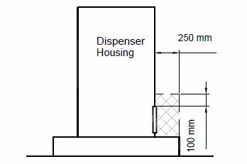
– The unloading site should be of “the offset fill point with access chamber” type and its design and area should be observed according to the following figures.
– The safety zone of the tank truck during unloading should be in accordance with the following figures and it is necessary to deactivate the station during unloading and to effectively protect the specified area.
– The unloading area must be equipped with a metal cap with sufficient strength and designed with a lock, and this cap can be removed only with special tools. This cap should be level with the adjacent surface and not obstruct passage.
– The unloading site must be equipped with an electrostatic discharge system and a suitable rake for discharge must be considered during the design.
– Connections in the unloading area must be quick-opening. - At the construction site of small stations, it is necessary to design and construct a fire-resistant concrete channel to protect the urban infrastructures that are located within the site (including telecommunication and electricity cables, gas and water pipes, etc.)
- All materials used in buildings, canopies, and the site must be non-flammable and approved by competent authorities.
- The area around the underground tanks, which are located in an isolated concrete pond, should be filled with wind sand in 50 cm layers while spraying and pounding. In addition, in order to prevent the infiltration of surface water into the reservoir burial pool, suitable moisture insulation should be used on it with the necessary bedding.
- All ducts of product pipes, power cables, and instrumentation should be filled with soft sand.
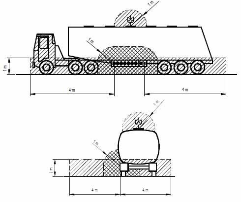
Classification of hazardous zone areas in filling stations
Hazardous areas refer to places where, due to the permanent presence of the product or the resulting flammable vapors or the possibility of its existence, the installation of electrical equipment to perform the work using tools requires special precautions and compliance with relevant standards.
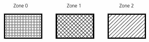
These areas are classified as follows:
| Zone 0 | An area where a mixture of explosive gas is permanently present or is expected to be present for a long time, or such conditions frequently occur many times in short periods. |
| Zone 1 | An area where, during regular operation, the presence of an intermittent or occasional mixture of explosive gas can be expected |
| Zone 2 | An area in which the presence of an intermittent or occasional mixture of explosive gas is not expected to occur during regular operation, or such a condition occurs very rarely and in a short period of time. |

Right: No vapor recycling system
Left: Equipped with vapor recycling system

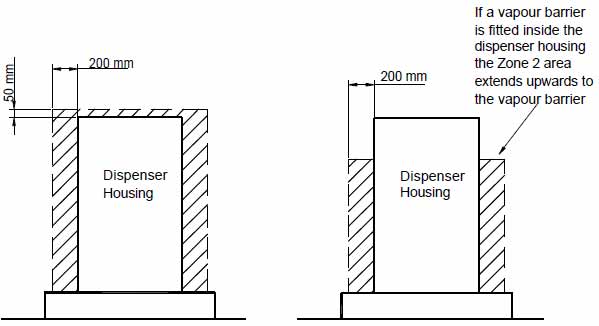
Right: Equipped with a steam barrier (air distance)
Left: No vapor barrier (air distance)

Right: No vapor recycling system
Left: Equipped with vapor recycling system

Above: No vapor recycling system
Below: Equipped with vapor recycling system
List of required drawings for a filling station
All design drawings should be prepared and submitted in accordance with the following list:
- Location map of the site, design, and construction details of the site
- P&ID drawings of the station (Piping and Instrumentation Diagram)
- Classification of danger areas
- Isometric plumbing drawings
- Design and construction drawings of the storage tank and installation details
- Drawings of the electrical distribution system
- Fire extinguishing and fire alarm system
- Drawings of the control system and instrument positioning
- Drawing of site ground connection for the station
- Drawings of the emergency stop system
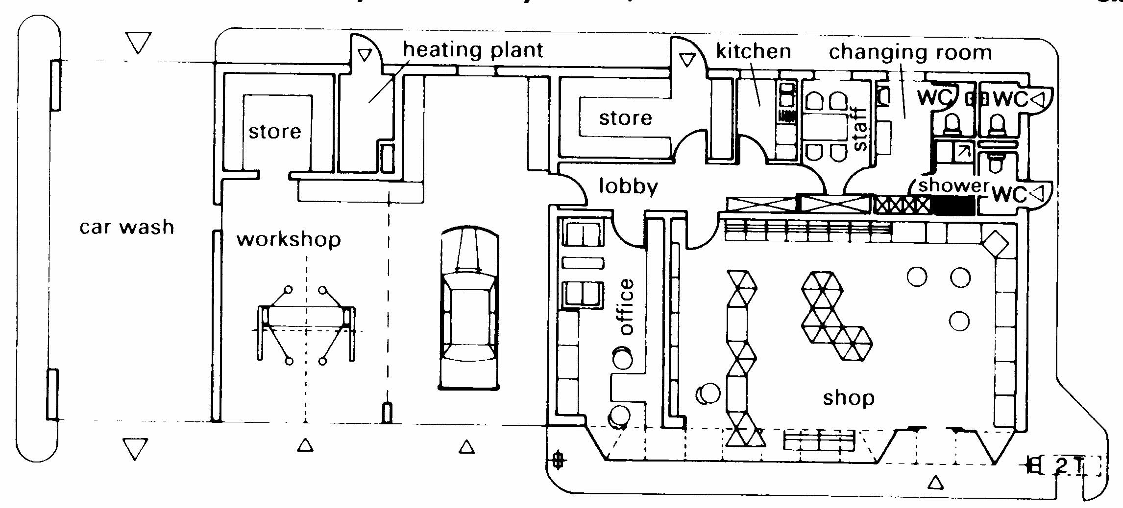
The architectural design of a filling station
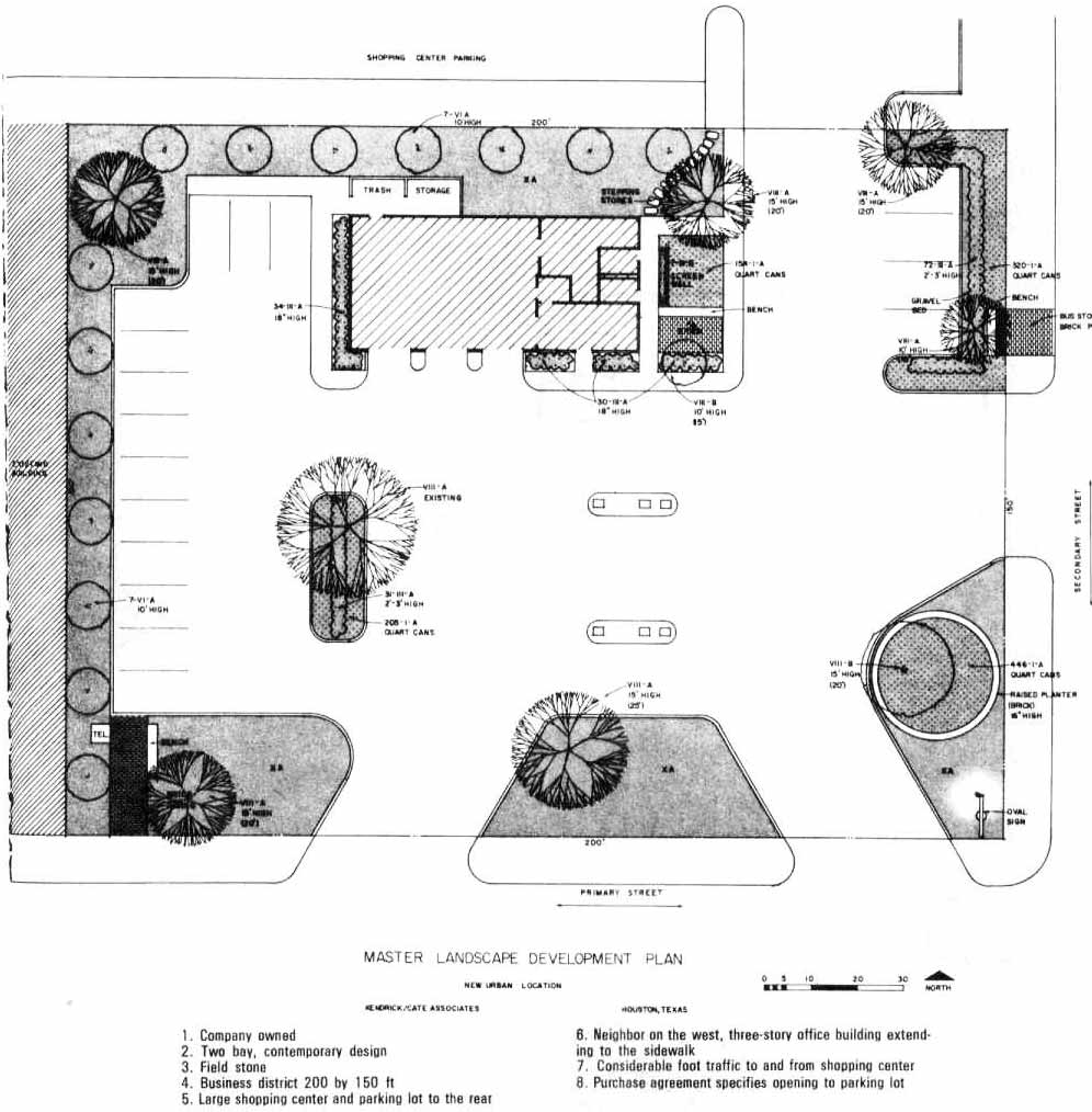
Filling stations may be combined with other commercial services. Therefore, the driver can obtain fuel, oil, service and maintenance, repair work, car accessories, and other goods all from one location.
If there are several filling stations on the same stretch of road, there should be >100m between any two or 250 m if the road carries heavy traffic.
On the open road, outside town limits, there should be one filling station for approximately every 25 km.
A plot size of about 800m2 is sufficient for a basic filling station, whereas one with service facilities will require about 1000 m2 and a large installation usually needs up to 2000 m2.
In the last ten years, the range of petrol available at filling stations has increased. Most stations now offer a variety of types of petrol as well as diesel. The design of filling stations should be flexible enough to accommodate future requirements.
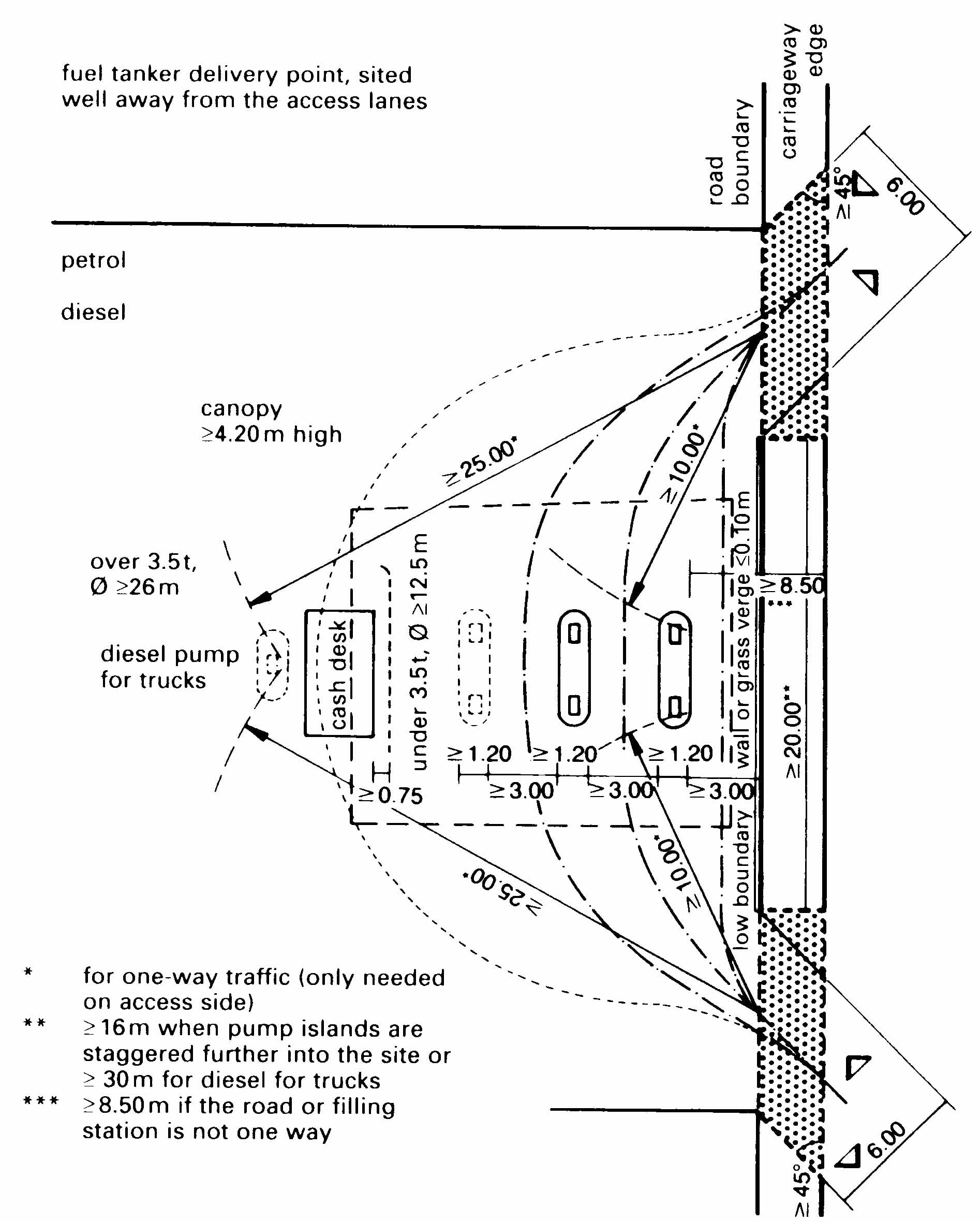
Filling stations should be easy to turn in, easily visible, recognizable from a distance, and located as near the road as possible. They should rarely be built in the town center, but rather on exit roads from the town, by-passes, and trunk roads and not where queues build up before a set of traffic lights. It is not good practice to site filling stations at street corners. A better answer is to site them just before a corner so that customers can drive out of the station into a side road.
Drivers should be able to refuel their cars, check, and, where necessary, top-up engine oil, cooling water, tire pressure, and battery fluid. Other services should be available, such as: checking the contents of the windscreen-washer bottle; cleaning the windscreen, headlights, and hands; purchasing goods; using telephones and toilets and other facilities; as well as facilities for car washing, vacuum cleaning, etc.
The building line and sightline, boundary distances, etc., shown in the development plan, must be strictly observed, as well as those terms and conditions that form an integral part of the building regulations.
Typically, there are rules which govern the following:
- the size of short-term/long-term parking spaces (i.e., 2.50m x 5.00m= 12.50 m2)
- the number of parking spaces required (this is dependent upon the number of employees working at the station, in the workshops, and on the pumps); and
- the space necessary for the queue at the automatic carwash (e.g., space required has to be sufficient for 50% of the hourly throughput of the carwash.
In accordance with the development plan, consideration must be given to the nominal dimensions laid down for motor vehicles, i.e.
| turning circle | car | 12.50 m |
| turning circle | truck | 26.00 m |
| vehicle width | car | 1.85 m |
| vehicle width | truck | 2.50 m |
| vehicle length | car | 5.00m |
| vehicle length | articulated truck | 18.00 m |
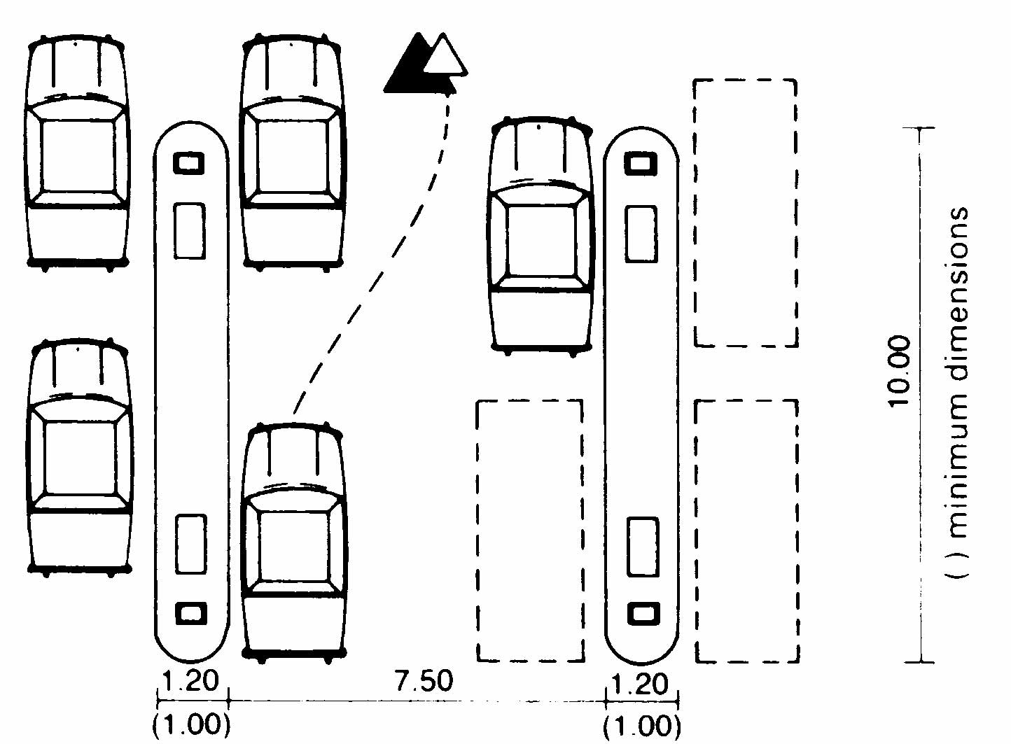
vehicle length Taking these figures as a basis, the appropriate dimensions of the pump islands and widths of the approach roads can be calculated.


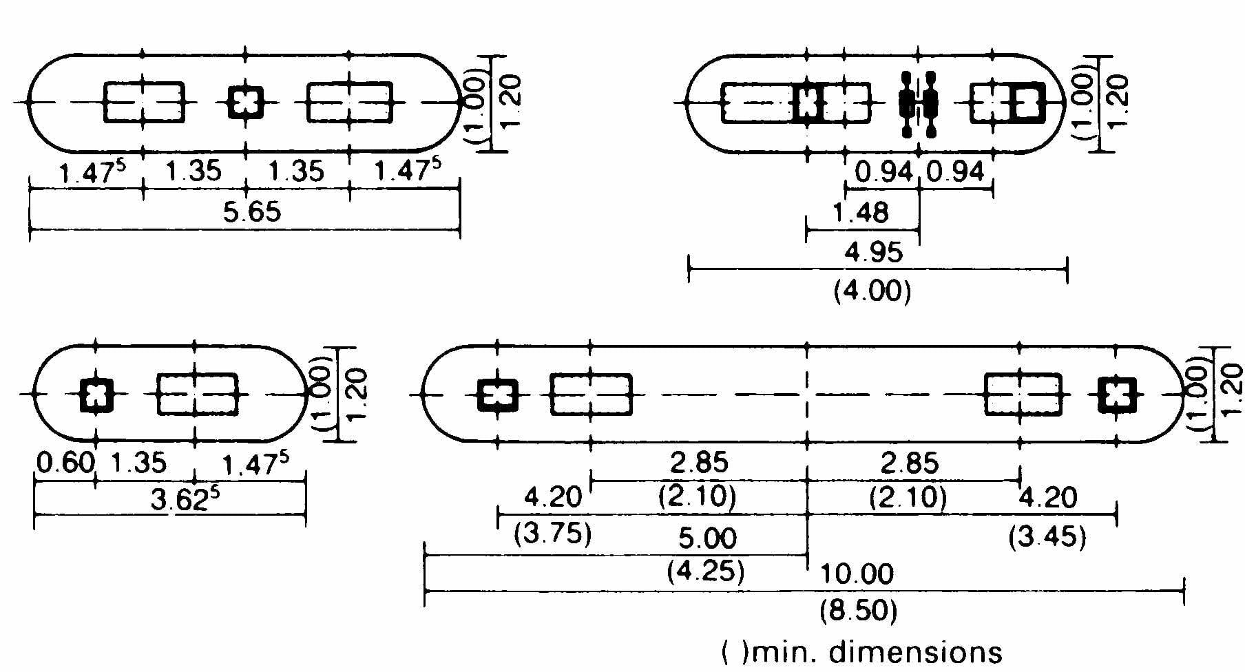

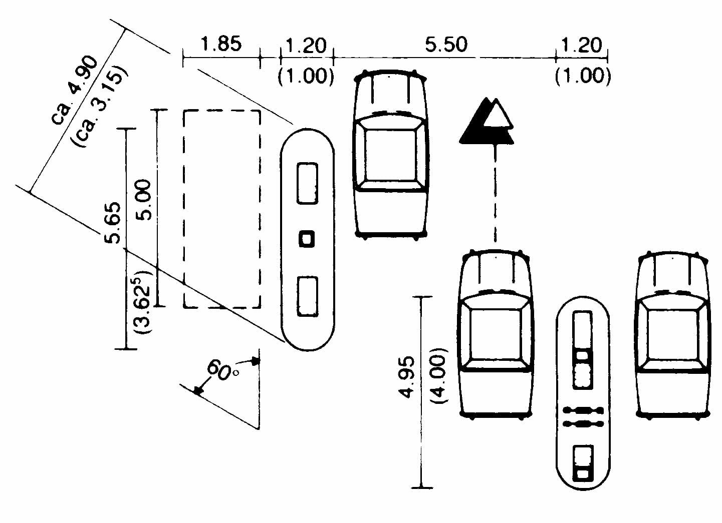
( ) minimum dimensions

(this requires good driving skills)


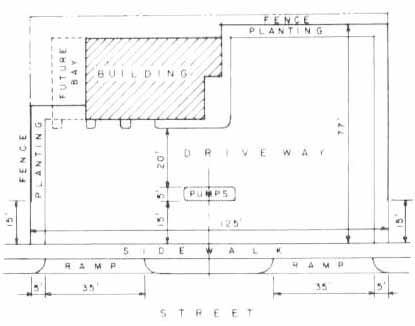
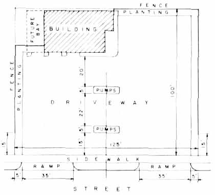
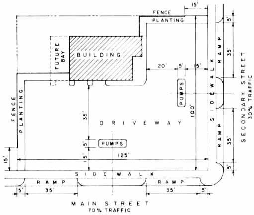
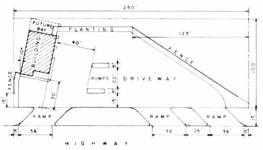
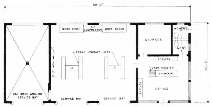
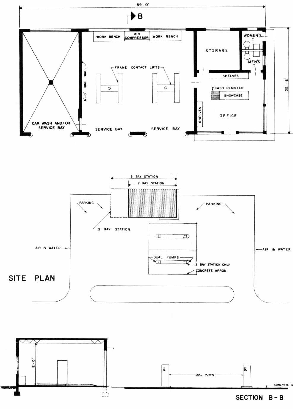
The next drawings show the standard plan of a major oil company for a two-bay service station. Additional bays may be added for larger installations. The Minimum recommended dimensions for bay door opening is 10 by 10 ft. Overhead-type doors are the most effective. Servicing pits have become obsolete; the mechanical lift is considered more practical.
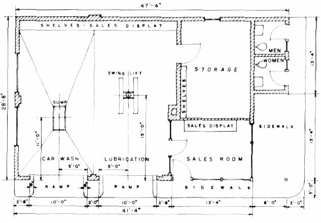
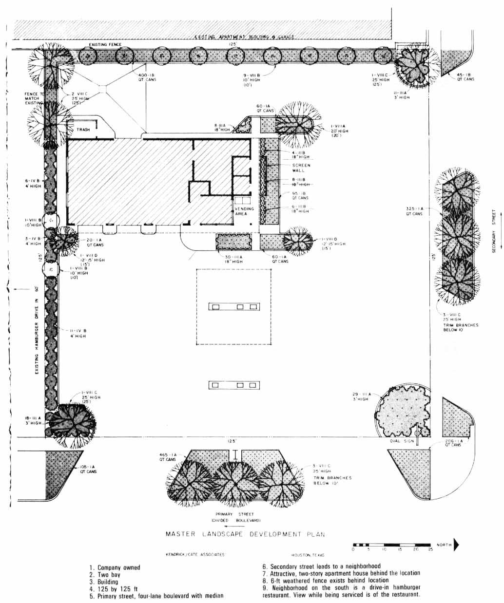
Compiled and edited by William J Cronin, Jr, Marketing Department. Humble Oil & Refining Co.
Compiled and edited by William J Cronin, Jr, Marketing Department. Humble Oil & Refining Co.
Related links:
Refrences
- BS 1710 : Specification for identification of pipelines and services
- BS 7430 : Code of practice for protective earthing of electrical installations
- BS EN 12285‐1 : Workshop fabricated steel tanks, Part 1 : Horizontal cylindrical single and double skin tanks for the underground storage of flammable and nonflammable water polluting liquids
- BS EN 13617‐1 : Petrol filling stations. Safety requirements for construction and performance of metering pumps, dispensers and remote piping units
- BS EN 13617‐2: Petrol filling stations. Safety requirements for construction and performance of safe breaks for the use of metering pumps and dispensers
- Callender, John Hancock. “Time Saver Standards for Architectural Design Data.” (1982).)
- Design, construction, modification, maintenance, and decommissioning of filling stations, APEA/IP joint publication, 2011, 3rd edition
- EN 14125 : Thermoplastic and flexible metal pipe work for underground installation at petrol filing installation
- IEC‐60529: Degrees of Protection Provided by Enclosures (IP Code)
- IPS‐E‐TP‐270 & IPS‐E‐IN‐100 & IPS‐E‐EL‐100 & IPS‐G‐IN‐270 & IPS‐E‐PI‐221 & IPS‐E‐TP‐100
- Neufert, Ernst, and Peter Neufert. Architects’ data. John Wiley & Sons, 2012
- NFPA 10: Standard for Portable Fire Extinguishers
- NFPA 101 : Life Safety Code
- NFPA 30: Flammable and combustible liquids code
- NFPA 30A: Code for motor fuel dispensing facilities and repair garages
- NFPA 72: National Fire Alarm Code
- NIOEC‐SP‐70‐11 & NIOEC‐SP‐70‐05
- Petrol filling stations guidance on managing the risks of fire and explosion, West Yorkshire Fire and Rescue Service, 2007
- UL 1316: Glass‐Fiber‐Reinforced Plastic Underground Storage Tanks for Petroleum Products, Alcohols, and Alcohol‐Gasoline Mixtures
- UL 971: Standard for safety non-metallic underground piping for flammable liquids